A Tutorial on Convolutional Coding with Viterbi Decoding
by Chip Fleming of Spectrum Applications
Updated 2011-06-21 11:11Z
Copyright © 1999-2014, Spectrum Applications. All rights reserved.
"Viterbi Algorithm (VA) decoders are currently used in about one billion cellphones, which is probably the largest number in any application. However, the largest current consumer of VA processor cycles is probably digital video broadcasting. A recent estimate at Qualcomm is that approximately 1015 bits per second are now being decoded by the VA in digital TV sets around the world, every second of every day." from "The Viterbi Algorithm: A Personal History" by G. David Forney, Jr., presented at the Viterbi Conference, University of Southern California, Los Angeles, March 8, 2005.
The purpose of this tutorial is to introduce the reader to a forward error correction technique known as convolutional coding with Viterbi decoding. More particularly, this tutorial will focus primarily on the Viterbi decoding algorithm itself. The intended audience is anyone interested in designing or understanding wireless digital communications systems.
Following this introduction, I will provide a detailed description of the algorithms for generating random binary data, convolutionally encoding the data, passing the encoded data through a noisy channel, quantizing the received channel symbols, and performing Viterbi decoding on the quantized channel symbols to recover the original binary data. Simulation source code examples of these algorithms follow the algorithm descriptions. (See the note at the bottom of this page regarding the soft-decision Viterbi decoder source code.) I have also included some example results from the simulation code. Since the examples are written in the C programming language, your ability to read C code would be very helpful to achieving a clear understanding. However, I have tried to provide enough explanation in the description of the algorithms and comments in the example source code so that you can understand the algorithms even if you don't know C very well.
The purpose of forward error correction (FEC) is to improve the capacity of a channel by adding some carefully designed redundant information to the data being transmitted through the channel. The process of adding this redundant information is known as channel coding. Convolutional coding and block coding are the two major forms of channel coding. Convolutional codes operate on serial data, one or a few bits at a time. Block codes operate on relatively large (typically, up to a couple of hundred bytes) message blocks. There are a variety of useful convolutional and block codes, and a variety of algorithms for decoding the received coded information sequences to recover the original data. The reader is advised to study the sources listed in the bibliography for a broader and deeper understanding of the digital communications and channel-coding field.
Convolutional encoding with Viterbi decoding is a FEC technique that is particularly suited to a channel in which the transmitted signal is corrupted mainly by additive white gaussian noise (AWGN). You can think of AWGN as noise whose voltage distribution over time has characteristics that can be described using a Gaussian, or normal, statistical distribution, i.e. a bell curve. This voltage distribution has zero mean and a standard deviation that is a function of the signal-to-noise ratio (SNR) of the received signal. Let's assume for the moment that the received signal level is fixed. Then if the SNR is high, the standard deviation of the noise is small, and vice-versa. In digital communications, SNR is usually measured in terms of Eb/N0, which stands for energy per bit divided by the one-sided noise density.
Let's take a moment to look at a couple of examples. Suppose that we have a system where a '1' channel bit is transmitted as a voltage of -1V, and a '0' channel bit is transmitted as a voltage of +1V. This is called bipolar non-return-to-zero (bipolar NRZ) signaling. It is also called binary "antipodal" (which means the signaling states are exact opposites of each other) signaling. The receiver comprises a comparator that decides the received channel bit is a '1' if its voltage is less than 0V, and a '0' if its voltage is greater than or equal to 0V. One would want to sample the output of the comparator in the middle of each data bit interval. Let's see how our example system performs, first, when the Eb/N0 is high, and then when the Eb/N0 is lower.
The following figure shows the results of a channel simulation where one million (1 x 10⁶) channel bits are transmitted through an AWGN channel with an Eb/N0 level of 20 dB (i.e. the signal voltage is ten times the rms noise voltage). In this simulation, a '1' channel bit is transmitted at a level of -1V, and a '0' channel bit is transmitted at a level of +1V. The x axis of this figure corresponds to the received signal voltages, and the y axis represents the number of times each voltage level was received:
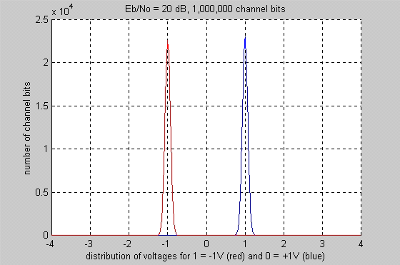
Our simple receiver detects a received channel bit as a '1' if its voltage is less than 0V, and as a '0' if its voltage is greater than or equal to 0V. Such a receiver would have little difficulty correctly receiving a signal as depicted in the figure above. Very few (if any) channel bit reception errors would occur. In this example simulation with the Eb/N0 set at 20 dB, a transmitted '0' was never received as a '1', and a transmitted '1' was never received as a '0'. So far, so good.
The next figure shows the results of a similar channel simulation when 1 x 10⁶ channel bits are transmitted through an AWGN channel where the Eb/N0 level has decreased to 6 dB (i.e. the signal voltage is two times the rms noise voltage):
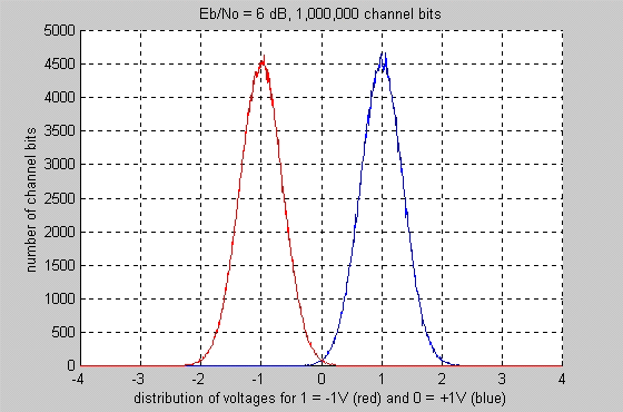
Now observe how the right-hand side of the red curve in the figure above crosses 0V, and how the left-hand side of the blue curve also crosses 0V. The points on the red curve that are above 0V represent events where a channel bit that was transmitted as a one (-1V) was received as a zero. The points on the blue curve that are below 0V represent events where a channel bit that was transmitted as a zero (+1V) was received as a one. Obviously, these events correspond to channel bit reception errors in our simple receiver. In this example simulation with the Eb/N0 set at 6 dB, a transmitted '0' was received as a '1' 1,147 times, and a transmitted '1' was received as a '0' 1,207 times, corresponding to a bit error rate (BER) of about 0.235%. That's not so good, especially if you're trying to transmit highly compressed data, such as digital television. I will show you that by using convolutional coding with Viterbi decoding, you can achieve a BER of better than 1 x 10⁻⁷ at the same Eb/N0, 6 dB.
Convolutional codes are usually described using two parameters: the code rate and the constraint length. The code rate, k/n, is expressed as a ratio of the number of bits into the convolutional encoder (k) to the number of channel symbols output by the convolutional encoder (n) in a given encoder cycle. The constraint length parameter, K, denotes the "length" of the convolutional encoder, i.e. how many k-bit stages are available to feed the combinatorial logic that produces the output symbols. Closely related to K is the parameter m, which indicates how many encoder cycles an input bit is retained and used for encoding after it first appears at the input to the convolutional encoder. The m parameter can be thought of as the memory length of the encoder. In this tutorial, and in the example source code, I focus on rate 1/2 convolutional codes.
Viterbi decoding was developed by Andrew J. Viterbi, a founder of Qualcomm Corporation. His seminal paper on the technique is "Error Bounds for Convolutional Codes and an Asymptotically Optimum Decoding Algorithm," published in IEEE Transactions on Information Theory, Volume IT-13, pages 260-269, in April, 1967. Since then, other researchers have expanded on his work by finding good convolutional codes, exploring the performance limits of the technique, and varying decoder design parameters to optimize the implementation of the technique in hardware and software. Consult the Convolutional Coding/Viterbi Decoding Papers section of the bibliography for more reading on this subject. The Viterbi decoding algorithm is also used in decoding trellis-coded modulation, invented by Gottfried Ungerboeck in 1982. This is the technique used in telephone-line modems to squeeze high ratios of bits-per-second to Hertz out of 3 kHz-bandwidth analog telephone lines.
Viterbi decoding is one of two types of decoding algorithms used with convolutional encoding-the other type is sequential decoding. Sequential decoding has the advantage that it can perform very well with long-constraint-length convolutional codes, but it has a variable decoding time. A discussion of sequential decoding algorithms is beyond the scope of this tutorial; the reader can find sources discussing this topic in the Books about Forward Error Correction section of the bibliography.
Viterbi decoding has the advantage that it has a
fixed decoding time. It is well suited to hardware decoder implementation. But
its computational requirements grow exponentially as a function of the
constraint length, so it is usually limited in practice to constraint lengths
of K = 9 or less. Stanford Telecom produces a K = 9 Viterbi
decoder that operates at rates up to 96 kbps, and a K = 7 Viterbi
decoder that operates at up to 45 Mbps. Advanced Wireless Technologies offers a
K = 9 Viterbi decoder that operates at rates up to 2
Mbps. NTT has announced a Viterbi decoder that
operates at 60 Mbps, but I don't know its commercial availability.
For years, convolutional coding with Viterbi decoding has been the predominant FEC technique
used in space communications, particularly in geostationary satellite
communication networks, such as VSAT (very small aperture terminal) networks. I
believe the most common variant used in VSAT networks is rate 1/2 convolutional coding using a code with a constraint length
K = 7. With this code, you can transmit binary or quaternary phase-shift-keyed
(BPSK or QPSK) signals with at least 5 dB less power than you'd need without
it. That's a reduction in
But there's a tradeoff-the same data rate with rate 1/2 convolutional coding takes twice the bandwidth of the same signal without it, given that the modulation technique is the same. That's because with rate 1/2 convolutional encoding, you transmit two channel symbols per data bit. However, if you think of the tradeoff as a 5 dB power savings for a 3 dB bandwidth expansion, you can see that you come out ahead. Remember: if the modulation technique stays the same, the bandwidth expansion factor of a convolutional code is simply n/k.
Many radio channels are AWGN channels, but many, particularly terrestrial radio channels also have other impairments, such as multipath, selective fading, interference, and atmospheric (lightning) noise. Transmitters and receivers can add spurious signals and phase noise to the desired signal as well. Although convolutional coding with Viterbi decoding might be useful in dealing with those other problems, it may not be the best technique.
In the past several years, convolutional coding with Viterbi decoding has begun to be supplemented in the geostationary satellite communication arena with Reed-Solomon coding. The two coding techniques are usually implemented as serially concatenated block and convolutional coding. Typically, the information to be transmitted is first encoded with the Reed-Solomon code, then with the convolutional code. On the receiving end, Viterbi decoding is performed first, followed by Reed-Solomon decoding. This is the technique that is used in most if not all of the direct-broadcast satellite (DBS) systems, and in several of the newer VSAT products as well. At least, that's what the vendors are advertising.
Recently (1993) a new parallel-concatenated convolutional coding technique known as turbo coding has emerged. Initial hardware encoder and decoder implementations of turbo coding have already appeared on the market. This technique achieves substantial improvements in performance over concatenated Viterbi and Reed-Solomon coding. A variant in which the codes are product codes has also been developed, along with hardware implementations. Check the appropriate sources listed in the bibliography for more information on turbo coding and turbo code devices.
Click on one of the links below to go to the beginning of that section:
Introduction
Description
of the Algorithms
Simulation
Source Code Examples
Example
Simulation Results
Bibliography
About
Spectrum Applications...
![]()
About Spectrum Applications...
Spectrum Applications was a technical consultancy specializing in wireless digital communications and related fields, founded in 1995, and closed in 2003.